How to Make a Flat (and Why Not To)
παθὼν ὁ νήπιος ἔμαθεν - Greek proverb (A fool learns by suffering.)
I've
stolen the title from ATMI in which the same caution is made to those
who would build a Cassegrain telescope. You will find this article to
read like a humble confession, describing how the author learned
considerably by
the suffering method. The hope is that, if the reader is intent on
pursuing this project, then perhaps my mistakes won't be repeated, and
that your results will be better and achieved more quickly.
Making
an
optical flat I believe is a sort of right of passage for opticians. It
is somewhat more difficult than the making of a moderate f-number
reflector, for several reasons. First, in making a telescope mirror,
the radius of curvature is
somewhat arbitrary, give or take an inch or so. You have no such
freedom with a flat: the curvature must be zero.
Second, to test the telescope mirror, one can use Foucault's or
Ronchi's method, with a minimum of equipment. But the testing of a flat
ideally requires the presence of a master
flat to test against; failing that, one must either resort to Ritchey's
technique (described below), or two more work pieces to provide a
three-way interference test (also described below).
On
the second point, I've tried both, and will describe my experiences.
All this took place over a period of a few years; it wasn't my priority
project, but I tried to set aside an hour every couple of days to keep
it moving forward. Mostly, it moved sideways, and often, backwards.
I
should mention that I built a Fizeau interference tester, which I'll
describe later on. I used it, together with a 3 inch master flat (1/10th wave)
to make several small flat mirrors to be used as diagonal mirrirs in
Newtonian telescopes or as star diagonals in refractors. I think my
experience with small flats made me think the 10 inch project wouldn't
be that much more difficult. Boy! Was I mistaken!
My
good-hearted friend, Jack Borde, of the Mt. Diablo Astronomical
Society, kindly gave me a couple of plate glass tool blanks, slightly
over 10 inches in diameter (26cm), and a slightly smaller 10 inch Pyrex
mirror blank. The Pyrex had a nasty chip in it, which led me to
choose one of the plate-glass blanks for my flat. The plate glass was
polished on both sides, so that it could be interference-tested either
face-up or face-down. The 3 inch master flat proved very useful. But wanting
to be able to test the entire flat, I decided upon Ritchey's method,
which I'll now describe.
Ritchey's Method

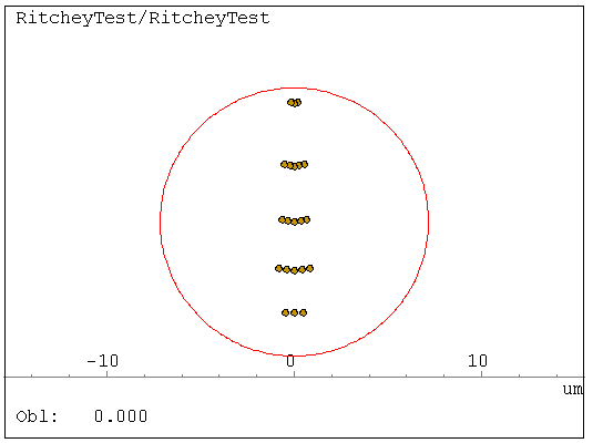
The
idea is simple: You first make as good a sphere as you can; it can be a
little smaller than the flat under test. In the example above, a 12
inch (300 mm) flat is being tested against an 8 inch mirror with a 2
meter radius of curvature. The "flat" has a convexity amounting to
about 1/2 wave (1 fringe) at the margin. The resulting astigmatic image
at the center of curvature is easily seen, even though the radius of
the sphere is shorter than Ritchey recommended. One uses the eyepiece
test, and should have a way of fine-adjusting the longitudinal motion
of the eyepiece so that the amount of astigmatism can be measured. In
this example, a movement of only about 1/4 mm outward brings the spots
into a horizontal pattern in the ray-trace above. A longer radius would
help spread this out.
What looked vertical in the above plot was
actually the best sagittal focus, y being in the plane of the tilt.
This required me to tell the software to tilt the flat 45 degrees about
the x axis. Are you confused yet? In my own setup, the y axis is
horizontal, so the blur would look to be horizontal. As I draw the
eyepiece backwards, the blur becomes circular, and then lines up
vertically. This tells me the error was convex.
If you memorize these facts, you can make sense out of the test. Meridianal means
in the plane of the tilt - y as illustrated above. z lies along the
optical axis, appearing horizontal in the layout diagram. x is out of
the page, and it is the sagittal direction. So now, I'll state the rules:
1) If the sagittal focus (sharpest in x) is farther from the mirror than the meridianal focus, then the work piece is concave.
2) If the sagittal focus (sharpest in x) is closer to the mirror than the meridianal focus, then the work piece is convex.
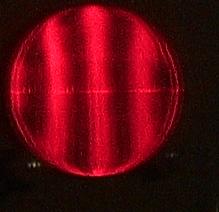
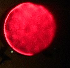
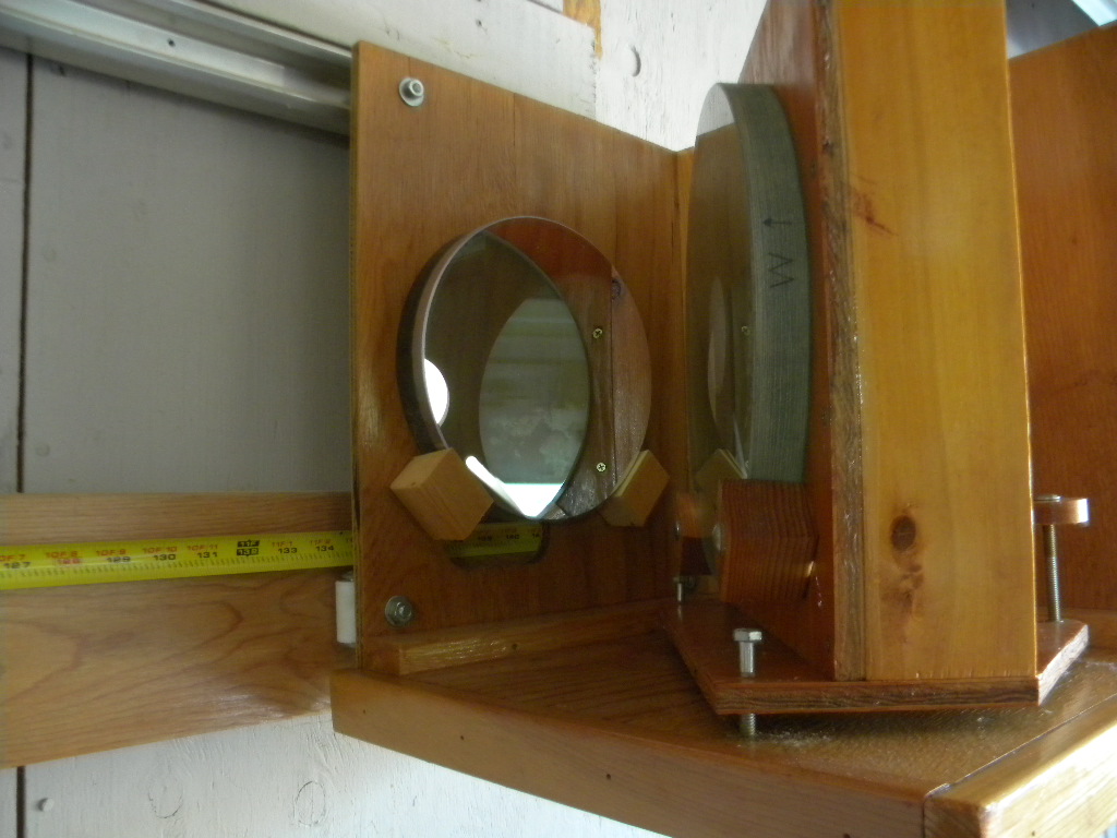
I
ground and polished an 8 inch mirror to a radius of about 3.8 m. I was
shooting for 150 inches and missed by about an inch. My final Ronchi
and Foucault tests are below. Also shown are the Ritchey test setup and
the front view of the light source and eyepiece. A camera can be
swung into place.
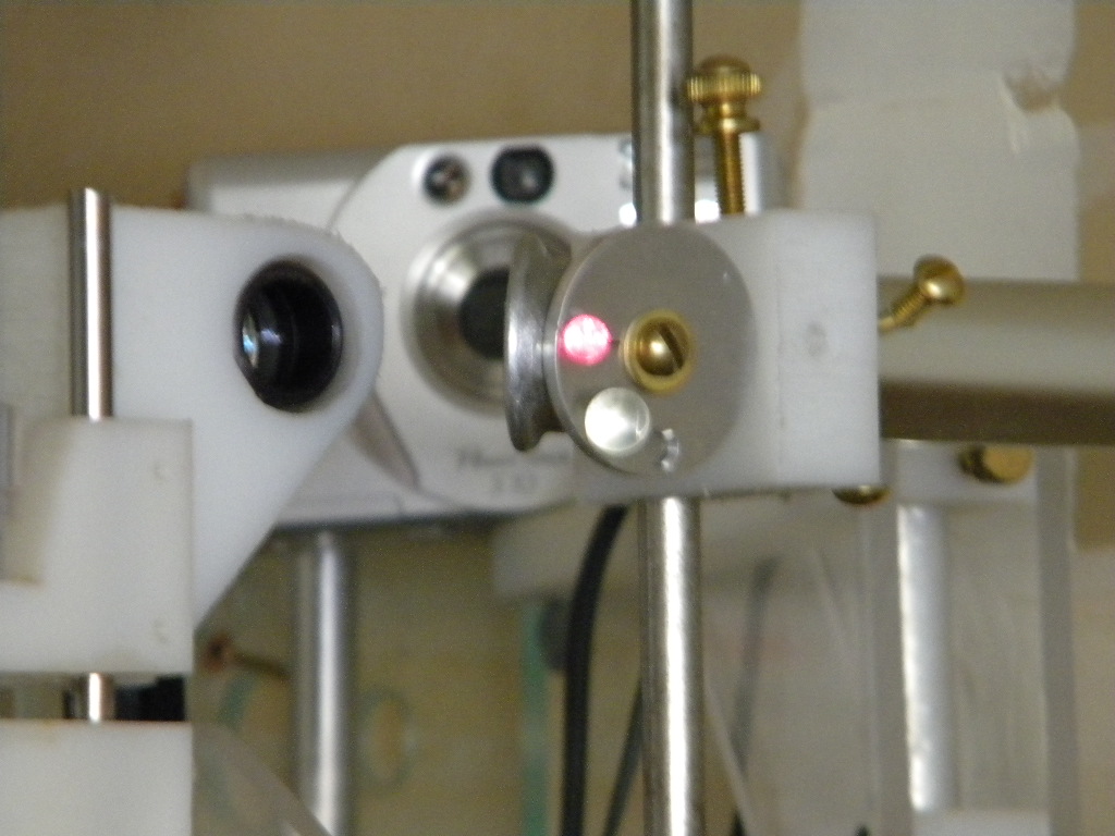
There
is a narrow turned down edge which I thought would not interfere with
using the mirror, and so I stopped there. I had the mirror aluminized,
For
the light source I used a laser pointer, located in the tube to the
right. It is reflected in a diagonal mirror, then comes to a wheel on
which are various pinholes, a slit, and beam-expander lenses; the
smaller one is currently lit up by the laser in the picture. For the
beam expander I wanted to use the objective from a microscope, but
found it had metric threads. My lathe isn't set up for metric screw
cutting, so I puzzled over how to mount it when a simple solution
occurred to me: Tap Plastics sells little plastic balls in various
sizes, and they appear to be pretty round. These did the job nicely;
however minor imperfections in the surfaces caused a multitude of
speckles and a somewhat confusing sight in the eyepiece. But
sitting in the middle of all this mess was a sharp line with
diffraction fringes.
The sharp line was neither horizontal nor
vertical, but ran off at an angle. Rotating the work piece resulted in
various odd shapes, and I concluded the blank wasn't a figure of
revolution. Also, the focus fell much closer to the work than I
expected, by some 16 inches! I put the other 10 inch blank to work as a
tool, and started grinding with 320 grit. An hour-glass pattern
appeared on the face of the work, indicating a surface more or less
saddle-shaped. I continued working the two disks, first with work on
top, then with tool on top, hoping to keep the shape more or less flat.
Once the tool and work were fully ground out with 320 grit, I checked
both with a spherometer. I made one around a Starrett dial guage
which an be read to a ten-thousandth of an inch, and probably can
be believed. I ground both faces of the work piece until I got
sphereometer readings of 0.0001 and 0.0002.
I also checked tool
and workpiece for flatness using a machinist's straight edge. This is
more sensitive, and a better way to evaluate the work. As I progressed
to finer and finer grades, I would only go on to the next grit if tool
and both surfaces of the work piece were seen flat with the straight
edge. After finishing the grinding with 5μ aluminum oxide, I made a
wood base for the pitch lap by gluing up several layers of
plywood, and then applying several coats of spar varnish. I made pitch
squares, as Texereau recommends. The pitch was Wilmann-Bell burgundy
pitch, which I boiled some time to produce a hard lap.
Texereau's
method results in very clean channels - right down to the wood. It is
much easier to keep these clear than those you try to chisel out of a
solid lap. Naturally, all won't come out the same thickness, and there
is a lot of hot-pressing and trimming ahead before the lap makes
satisfactory contact. I have taken to using cerium oxide for the
polisher. It works somewhat faster than conventional rouge, and is less
messy. I have very sensitive skin, and so I always use disposable
gloves when working with the stuff.
Once I had enough of a
polish to test, it was back to the Ritchey test rig. The workpiece
showed considerable astigmatism. By ray-tracing, I determined that the
figure was 4.5μ concave, so it was reassuring that the straight edge
wasn't far off, and this amount of curvature (9 fringes) can be
corrected by polishing. Well, a lot of polishing! Flattening a
concave surface is more difficult than you would think. If your lap is
equal in size to the work, you have to resort to overhang strokes with
the work on the bottom. This will waste a lot of polisher, but the only
course of action available. If you have access to an over-sized lap
(and an adequately flat piece of glass to press it with) things would
go faster. Various writers swear by using an over-sized lap, but that
wasn't possible for me.
Now I began to be disenchanted with the
Ritchey test. No fault of Ritchey's, but I had the problem that every
time I plopped down the work piece in its holder, I would disturb the
adjustment and have to re-align the glass so that the image was visible
in the eyepiece. For this, the laser came in handy; I would rotate the
wheel moving the beam expander out of the path, and exposing a large
pinhole. This allowed the laser beam to stay small, and the beam could
then be seen shining somewhere on the wall behind me. I could then
adjust the screws to bring the beam to shine on the eyepiece, and then
I was lined up. Fine. But always with a slightly different angle of
incidence with respect to the spherical mirror. The amount of
astigmatism is somewhat sensitive to this angle, expecially when the
work is pretty far from flat. And so after a spell of polishing I was
sometimes seeing more of the error I was trying to correct, and it was
impossible to tell whether maybe I wasn't using the proper stroke.
Another
complication which was sure to arise was the presence of zones on the
work piece. I could look for these by substituting an LED light source
for the laser, selecting the slit on the wheel, and using a knife edge
in place of the eyepiece. This, indeed, showed me that there was a
broad "rolled edge" on the blank and also a "hole" in the middle. The
cure for a hole is to press the lap with a small piece of waxed paper
in the central part, and then polish with the usual 1/3 diameter
stroke, alternating work on top (WOT) or work on the bottom (WOB). The
hole proved to be very persistent, and I expended several hours trying
to get rid of it.
From time to time, I placed the 3 inch
master down on the work piece and slid it under my Fizeau fringe
viewer. After the hole was considerably subdued, there remained about a
5 fringe turned down edge about 1/2 inch wide. Ritchey tested about 5mm
concave (longitudinal aberration). As best I could make out from the
small master, the profile looked something like this:

I
was making more sense out of this piecewise interference testing
than I was from the Ritchey setup. But I longed for a full-sized master
to test against. But wait a minute! The whole point of the
exercise was to create my own 10 inch flat. If I went out and bought
one, then, why was I wasting my time making one?
Well, the
remedy is of course to make 3 flats, testing all 3 pairs against one
another. ATM1 shows you how to compute the concavity or convexity of
all three, by solving 3 simultaneous equations. The same idea can be
applied zonally, and I'll explain how this is done. Let the work pieces
be designated W1, W2, W3. W1 is the work piece I had been
testing, and it was fully polished out. W2 was the tool, and at this
stage it was fine-ground with 5μ emery, and polishing could begin. W3
was the somewhat damaged Pyrex blank. It had been rough-ground on the
slightly wider side, but that side had a nasty chip in it about 3/4
inch wide. The other side had been fine-ground, and I was able to
polish it. I made a second lap, this time using honeycomb foundation
for the polisher, which I worked with cerium oxide. Eventually, I had
W2 and W3 well enough polished I could test them.
Now I'll describe the Fizeau tester.
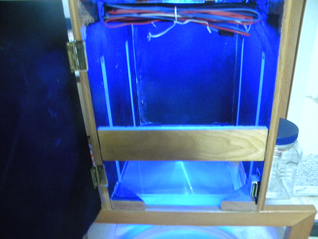
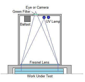
It
is simply a box with an open bottom, set upon legs to straddle the work
being tested below. An 8 1/2 X 11 inch Fresnel lens sits near the
bottom. (These inexpensive magnifiers are sold by Staples office
supply.) There are slotted metal channels intended for bookcase
shelves; I can place clips in the slots meant for shelving, only to
support Fresnel lenses at various heights within the box. The focus of
the Fresnel lens is near the top center, where I have a peephole
covered with a piece of green plastic. The light source is a near-UV
"bug light" intended for an insect trap; these lights use mercury vapor
which emits (in addition to blue and UV) a strong green line, which
provides excellent contrast for interference fringes. The lamp is
slightly displaced from the viewing hole which is also displaced from
the center line so that the peephole receives a strong reflection from
the work under test. Extra lenses can be inserted to accomodate curved
surfaces; I was able to test a Cassegrain secondary against a concave
test plate this way.
Now, the technique: I place paper strips on
one of the work pieces and lay the other carefully down on top, and
slide the two under the legs of the tester. I work one or more of the
paper strips until I see a number of interference lines (hopefully,
lines). I like to set the paper wedges up so that the lines run left to
right, and when I press on the top workpiece on the edge facing me, the
fringes tend to run closer together. If they go the other way, I rotate
the work 180 degrees. That way, what I'm seeing are coutour lines
representing the gap between the surfaces. "Uphill" is up in my view
through the peephole, so that if you have a concave deviation, the
lines curl up at the edges. I lay a steel rule across the work and
carefully line it up so that it is tangent to one of the (usually) wavy
lines near the center. I make a careful sketch of the deviations of the
fringe from the straight edge to scale on squared paper, usually with
one square representing a fringe vertically, and the radial distance
marked off horizontally. I do this for W1 against W2, W1 against W3,
and W2 against W3. Usually, I consider the zone at r
= 0 to have a value of 0 fringe deviation, and line up the straight
edge accordingly. One can easily see the rulings on the steel rule, and
so it is easy to make the sketches to scale. Now, consider that
at a particular zone r the test of W1 against W2 yields a reading of a in tenths of a fringe above the straight edge (negative, if below). So, if, say at r=2 inches from center I have an error of half a fringe, I score this as a "5". Now, let the error for that same zone be b when we test W1 against W3. And let the error be c when we test W2 against W3. Now, we can find out exactly what the actual error for each surface is by solving the equations:
          W1 + W2      = a
          W1      + W3 = b
               W2 + W3 = c
which has solutions:

          W1 = (a + b - c)/2,
          W2 = (a - b + c)/2,
          W3 = (-a + b + c)/2.
Here is an actual example of such a calculation:
Zone   a    b    c    W1   W2   W3   W1+W2  W1+W3  W2+W3
0.0    10   10   -7   14   -4   -4     10     10    -8
1.0    10    8   -8   13   -3   -5     10      8    -8
2.0     6    5   -5    8   -2   -3      6      5    -5
3.0     5    0    0    3    3   -3      6      0     0
4.0    10    0    2    4    6   -4     10      0     2
5.0    20    0    0   10   10  -10     20      0     0
The
last 3 columns can be omitted if you do this calculation with a
spreadsheet; I include them because I was doing it with a calculator
and wanted to have a check. When I divided by 2, I ocassionally had to
round; I always rounded to make the result look bad, so the check sums
don't always agree with the inputs a,b,c.
As
luck would have it, after combatting a broad and deep rolled edge (face
down, very short, rapid W strokes, no offset), W3 shaped up to be
rather flat. I finally compromised with a very slight and narrow turned
down edge, but W3 was good enough so that I didn't have to resort to
the above calculations except in the very end to check things. So I
could test W2 against W3 and pretty much know what was wrong - it was
W2. Likewise W1.
Both W1 and W2, the plate glass work pieces,
exhibited a profile somewhat like the one I illustrated above,
with an "up" edge almost at the margin, and a narrow turned-down edge
at the last. This is a generally concave surface, and the only cure
with the same-sized tool was to work it face up, with approximately a 4
inch overhang, and short 1 1/2 to 2 inch straight strokes. It seemed
like it was taking way too long to correct these two blanks, and I
began to suspect some strain in the glass might be the cause. So I
built a light-box with a sheet of Polaroid in its window, propped up W2
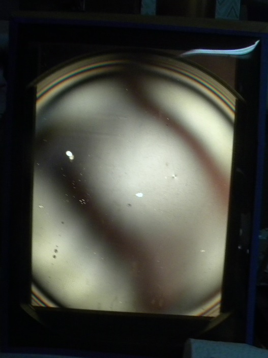
leaned
a second sheet of Polaroid against it, but rotated 90 degrees to the
first sheet, and snapped a photo of it. The two broad shadows weren't
so prominent to the eye, but the camera seemed to favor them. What was
more obvious were the sets of rings near the edge of the workpiece, and
these I found went all around the edge pretty evenly. I tested W1 and
found almost the same pattern of rings. My guess is that when the plate
was cut to make a circular disk, some strain was introduced into the
glass.
One rather warm summer day I went into the shop ("shop"
being our garage) where I had been pressing a small pitch tool onto W2.
It had stuck. Usually, this isn't much of a problem; I
tapped the tool with a mallet. Not budging. I escalated the
game by using a wood-worker's clamp. Not budging. While the
clamp was still applied, I tapped the tool again with the mallet. This
time, it sprung loose. I wiped up some of the pitch that stuck to the
work piece, and decided to test it. The last test showed about 2
fringes of concavity. This time I saw 14 fringes!
Now,
Russell Porter had a solution for this sort of thing. You seek out a
stout hydrant, and hurl the workpiece against said hydrant, with as
much force as possible. Repeat, if necessary, to get the disappointment
out of your system. Instead, I walked away, and left it there on the
tester, where I had placed it against W3. Took up another project for
the rest of the day, and then enjoyed a good glass of my favorite
Chardonnay.
The next moring, with some trepidation, I turned on
the lamp in the Fizeau tester. Lo and behold! Now the workpiece
was only out about 3 fringes. It had gradually settled down. It still
took several hours of the overhang stroke to bring it flat. (Its
cousin, W1, meanwhile had come to rights with the overhang treatment,
but does have a wide (1/2 inch) rolled edge of 1 fringe. I eventually
brought W2 to the same degree of imperfection, and the final results
are displayed below.
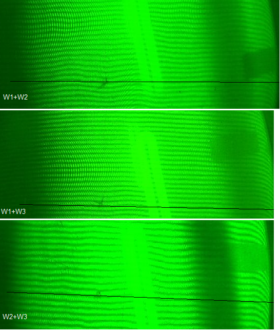
I believe W3 is probably good to 1/10 wave, except for its edge.
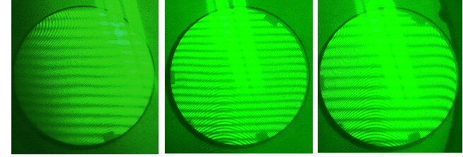
Here,
it is seen against the 3 inch master, in views of center, mid, and
edge. The tests against W1 and W2 show no general concavity or
convexity, and so at this point I'm satisfied.
It will be
interesting to see whether W1 and W2 hold their figures over time.
Meanwhile, W3 will be suitable for null-testing of any further optics I
make.
Solving Problems
Here are a few problems I ran into, and so will share my solutions with you.
1.
The Fizeau viewer wasn't wide enough, or putting it a little
dirrerently, the illuminated region on the disks under test was too
small to see the whole width. This had the unfortunate result that I
was making a very fine V-shape on W1, which looked flat over what I
could see. The obvious solution was to place the disks on the center
line. (By the way, the center is marked with an indelible pen on the
back of each work piece.) Then, laying a straight edge across the work,
I could see the "V" very clearly. So, that became the starting
procedure. Once I had the straight edge cutting an equal number of
fringes on each side, I then very gently shifted the work over until I
could see the edge. The V took a long time to correct!
2.
Fixing a hole I found takes a very large amount of polishing.
Easy to create, hard to correct, because you have to excavate glass
down to where it's level with the bottom of the hole. The remedy was
first to make a mask out of waxed paper equal in diameter to the outer
edge of the hole. I then took short, "W" strokes, as illustrated:
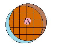
The
path of the center of the work, face down, is shown. That is what I've
called WOT - work on top (facing down). Looking through the back of the
glass, one can see that the central region that was masked is not in
contact; the polisher in the liquid is seen moving back and forth, but
the working facets are in full contact, and you can see the pitch.
After this has gone on for half an hour or more, you won't see much
progress on the hole, but there will be a substatntial raised edge on
the work. Now this needs to be treated by working the work piece
face up ("WOB" - work on bottom), tool face down, with a large offset
(4 inches in my case) and moderate stroke, as illustrated. It isn't
necessary to press out the center -- leave it depressed, it will be
needed that way.

Now, we'll have this sort of shape as seen with the fringes:

The
center line is on the left. What you have is a sort of perverse
"doughnut." That is handled by local polishing with a
sub-diameter lap. You could perhaps even use HCF, but I made one out of
pitch, about 6 inches in diameter. With work face-up, this is worked on
the crest of the doughnut.
What we wind up with is still a hole
in the middle, but it should be somewhat diminished. Now, the full lap
is worked, again WOB, only now with less an offset, maybe about halfway
to the edge. This will smooth things, but there is still a hole.
Therefore, we repeat the entire sequence. I needed about two
repetitions to make my hole go away. You can see there is still a trace
of the doughnut on both W1 and W2 in my interferograms, and the W1+W2
together show it clearly, as this doubles the error. The final
treatment with full lap removes most of the ripples left by the small
lap. I avoided using the small lap except for this purpose.
3.
How to make a hole: You start with a hill in the center,
which I think came about from poor contact in the center. The treatment
is nicely shown by Texereau in his chart on "touching up."

Hill
treatment is "heap powerful medicine." You'll notice the stroke is
tapered off as one brings the work closer to center. Probably one trip
around the barrel is enough. Stop and test before proceeding. It takes
very little work to remove a hill, and very little more to make a hole.
I fell for that one hook, line, and sinker. Adding to that, my plate
glass work pieces tended to "snap back" into the raised-edge
configuration whenever I worked the center. Still scratching my head as
to why, but that's what happened. Porter's advice about the hydrant is
not misguided.
References
Books
Ingalls, Albert G., ed, Amateur Telescope Making, Book One, Scientific American, Inc., New York 1981 (4th ed.).
Ingalls, Albert G., ed., Amateur Telescope Making, Book Two, Scientific American, Inc., New York 1959 (1st ed.).
Ingalls, Albert G., ed., Amateur Telescope Making, Book Three, Scientific American, Inc., New York 1953 (1st ed.).
Roark, Raymond J., Formulas for Stress and Strain, McGraw-Hill, N.Y. 1965.
Strong, John, et al., Procedures in Experimental Physics, Prentice-Hall, Englewood Cliffs, NJ, 1938.
Texereau - How to Make a Telescope, Allen Strickler, Transl., 2nd ed. Willmann-Bell, Inc.,Richmond, VA, 1984.


