Wright Schmidt Telescope
J. A. Hudson
Contents
1. The Wright Stuff
2. The Correcting Plate
3. The Primary Mirror
4. The Mounting
1. The Wright Stuff
In the 1930's there was a lot of excitement in the astronomical
community over the recent invention by Bernhard Schmidt of the camera that bears his name. The primary mirror was a sphere, and
could be made as fast as f:2, or even f:1.5, meaning that only a
moderately long exposure could reach very faint stars. The spherical
aberration (so named because a sphere cannot render a sharp image of a
star, but instead creates a blur) was compensated by a thin plate
located at the mirror's center of curvature which was figured to a
curve, described by a fourth-order polynomial, which exactly cancelled
out the aberration of the primary.
The fact that the
Schmidt's entrance pupil, the correcting plate, was located at the
center of curvature meant that objects off the central axis would be
imaged almost as sharply as they would on center, so the Schmidt was
not only a fast camera, but it was wide-field as well, making it a fine
instrument for exploring our Milky Way, with its wealth of nebulae,
star clusters, and obscuring dust. Moreover, it was an ideal instrument
for doing deep-sky surveys, such as the Palomar Sky Survey.
There are several problems with the Schmidt configuration which make it
unsuitable for being an amateur's telescope. First, the field of view
is strongly curved, meaning that photographic plates had to be bent in
order to make use of the wide field. (They would occasionally break!)
This could be overcome by means of a field-flattening optic near the
focus. Next problem is tube length. If you want a moderately fast
Schmidt for visual (as well as photographic) use, you probably want to
make the f-number come out to around 4, where ordinary eyepieces can
work better. But this means a tube twice as long as the focal length,
since the corrector lens has to lie at the mirror's center of curvature
(always twice the focal length). Finally, one needs to bring the light
out to the side for visual use, so a sizeable secondary mirror is
required.
Franklin B.Wright proposed an alternative
design, which he described in Amateur Telescope Making, Book Two.
Instead of a spherical mirror, his design calls for an oblate sphere,
while the curves on the correcting lens are made stronger than in a
Schmidt of the same f-number. This results in a flat field, albeit
limited by astigmatism to only a couple of degrees of field. But the
corrector is located, not at the center of curvature, but at the focus.
The more limited field is fine for most eyepieces, and the few Wright
telescopes I've read about operate at about f:4.
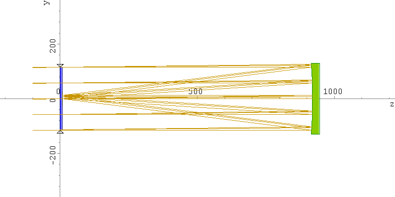
Fig. 1. Layout of a 9 inch f:4 Wright telescope
The prescription for the above telescope is as follows:
# Wavelengths
lambda     F
lambda     d
lambda     C
# Object Points
object     inf     0.000    0.000
object     inf     0.500    0.000
object     inf     0.750    0.000
# Glasses
Glass      AIR
Glass      523564
# Medium throught object space
medium     AIR
# Surface data
stop       228.60     0.00  1 flat
refr       230.00     9.50  2 polynom  3.03030E-06  -1.53410E-10  -7.62100E-17
refr       230.00   910.70  1 flat
refl       260.00  -911.70  1 polynom -2.73420E-04  -4.03550E-11  -8.04050E-18
screen      50.00     0.00  1 flat
This
formula follows exactly the formulae given by Wright in his paper, and
this pretty well describes my own Wright telescope. The glass
designation 523564 means nd = 1.523 and Vd
= 56.4, the parameters for
Pittsburgh Plate Glass "Shadowgraph Crown." The units are in mm. for
linear dimensions; angles are expressed in degrees. For each
surface, the type of surface is followed by its diameter (assumed
round), distance to next surface, index in the table of glasses (AIR=1
here), and the shape of the surface. The polynomial surfaces give the
coefficients for r2, r4, and r6. The following are ray-trace
results:

Fig. 2. Wavefront aberrations of the f:4 Wright telescope
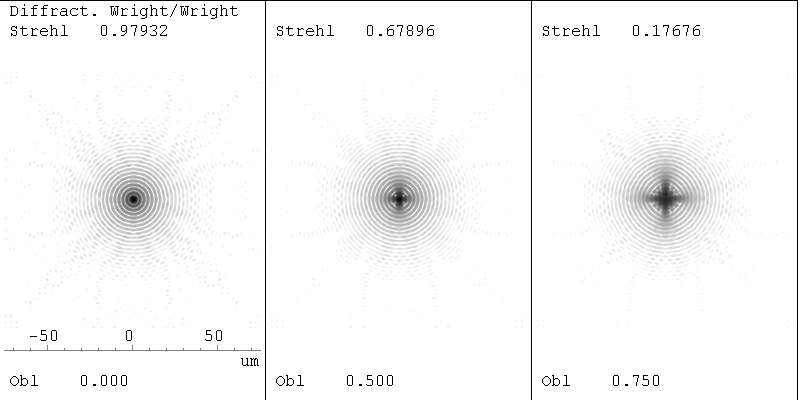
Fig. 3. Diffraction images for the f:4 Wright telescope
Note
that astigmatism is the limiting aberration for off-axis images. (This
is true also for the Schmidt; however, these only become a problem at
much larger field angles.) So we see the Wright f:4 is good out to
about 1/2 degree, and certainly acceptable photographically at 3/4
degree and even beyond.
Wright's original equations are these:
s = -(F-M) r2 / [2(n-1)EF] + M r4 / [16(n-1)EF3] + (4E+F)M r6 / [192(n-1)E2F5],
x = [E-(F-M)] y2 / (4EM) + [M-(F-M)] y4 / (32EM 3) + (E+M)M y6 / (384E2M5),
F-M = (3k2/64)[1 + 0.08k2]F,
k = D/F.
Here, s is the deviation of the lens surface from flat; likewise x is the deviation of the mirror's surface from flat. F is the focal length, D the diameter of the corrector (so the f number is F/D), M the distance between center of mirror and focus, E the separation of lens from mirror, and r and y
both stand for radial distances from the centers.Wright's sign
convention is exactly opposite to that chosen by the software for the
prescription above, but I wanted to present his equations exactly as
published.
The configuration I've described
is my own 9 inch Wright. It is a delight to use with a wide-field Erfle
eyepiece. Photographically it works well, too, although I've thus far
not invested in a camera that can accomodate the full field.
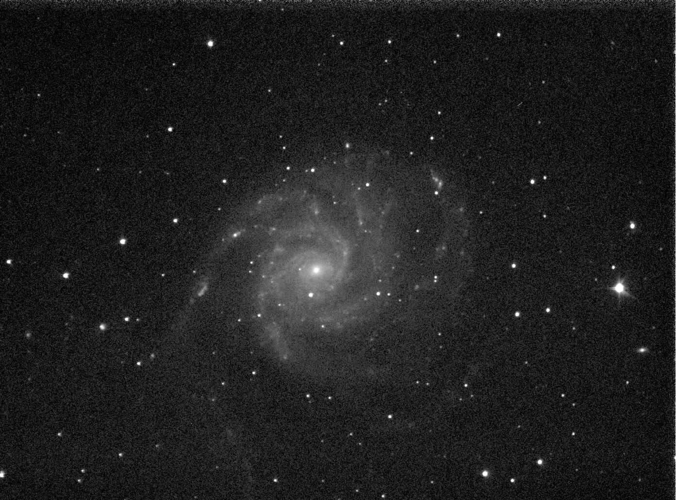
Fig. 4. M101 taken with Atik 16 HR with 9 inch Wright
My friend, Bob Bolster, and I both undertook the making of Wright
telescopes. His was a 12 inch, and mine a 10 inch, which I found worked
much better at a 9 inch aperture, avoiding vignetting and not an
altogether perfect job of fabricating the optics. I think Bob's 12 inch
turned out somewhat better.
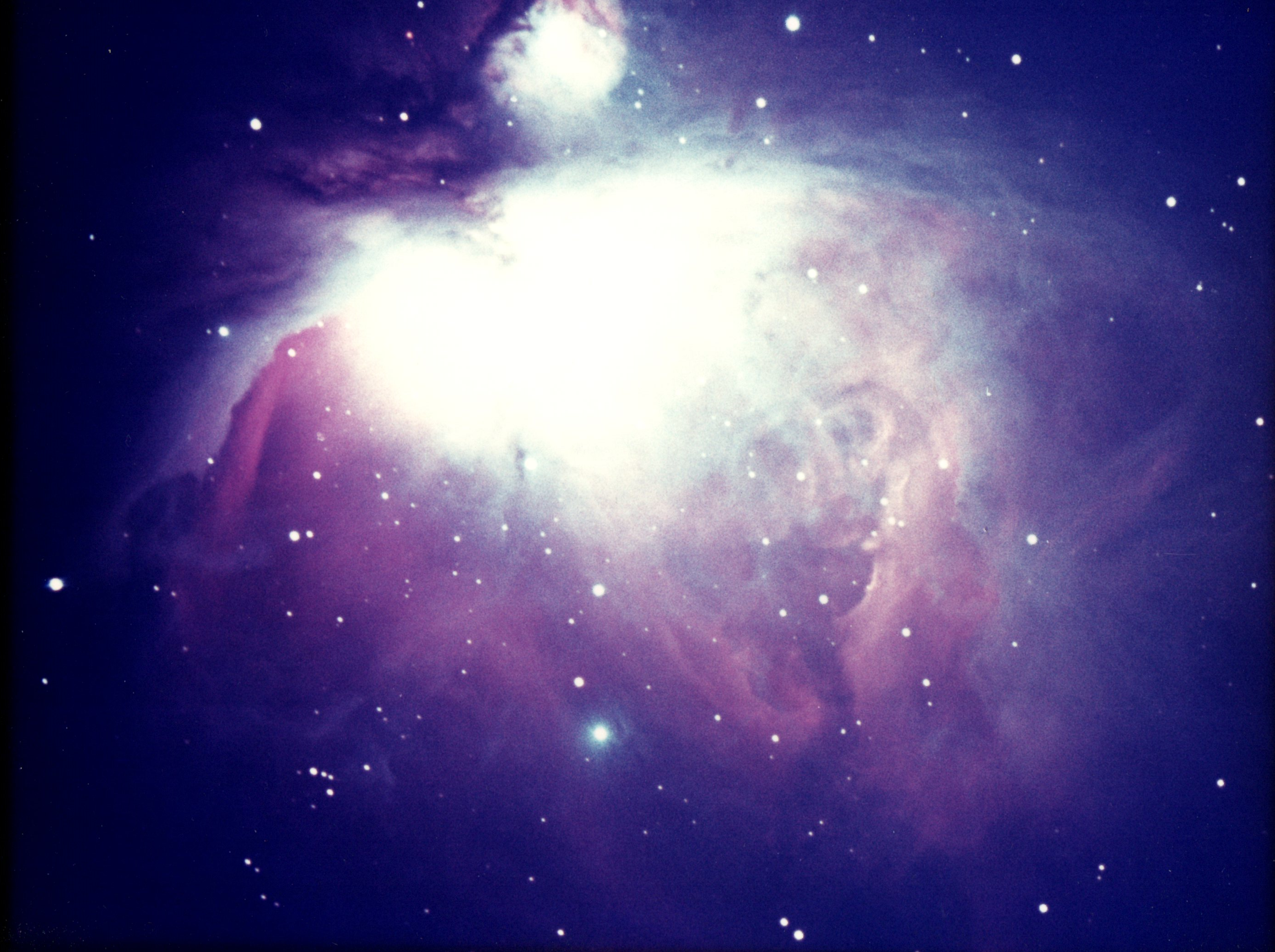
Fig. 5. M42 taken by Ken Short, using Bob Bolster's 12 inch Wright at Hopewell Observatory
2. The Correcting Plate
Of course, how to go about making these strongly aspheric surfaces?
Bob and I set about the following strategy: We would first finish
my 10 inch primary mirror to as good a sphere as we could. Setting this
up for testing at its center of curvature, we then placed each of the
correctors in front of the sphere, and measured zones, much as you
would figuring a paraboloidal mirror.
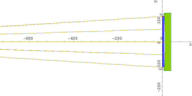
Fig. 6. Layout for testing correcting plate against spherical mirror.
The longitudinal aberration plot for this setup is shown here:
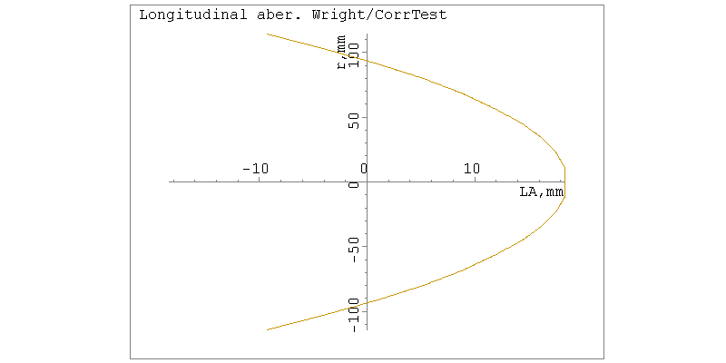
Fig. 7.
Longitudinal aberration for corrector in front of spherical mirror
The prescription for this ray-trace is as follows:
# Wavelengths
lambda     d
# Object Points
object     -1818.700    0.000    0.000
# Glasses
Glass       AIR
Glass       523654
# Medium throughout object space
medium     AIR
# Surface data
stop       228.60     0.00   1 flat
refr       230.00     9.50   2 polynom     3.03030E-06  -1.53410E-10  -7.62100E-17
refr       230.00     4.00   1 flat
refl       260.00    -4.00   1 sphere     -1830.0000
refr       230.00    -9.50   2 flat
refr       230.00 -1818.7    1 polynom     3.03030E-06  -1.53410E-10  -7.62100E-17
screen      50.00     0.00   1 flat
The
common convention followed here is that light rays move from negative
to positive coordinates, the z axis being chosen as the optical axis.
Thus, the object point is situated at z
=-1818.7 mm. The stop is at the lens, since it limits the bundle of
rays coming in. Next is the front surface of the correcting plate,
whose equation is given in the form z = a2 r2 + a4 r4 + a6 r6. The coefficients are such that the value of z
comes out in millimeters. The sphere is the test sphere of radius 1830
mm. Note here that the convention for calculating the LA
(Longitudinal Aberration) follows the same sign convention. Thus, rays
coming back from the lens under test at increasing radial distance from
the center are focused farther and farther toward -z,
meaning back towards the observer whose eyepoint is near the object
point. And so, the appearance of the lens under the Foucault test is
just like that of a hyperbolic mirror, with about 4 times the
correction as that of a parabolic mirror at f:4. In our test setup,
knife edge and slit moved together, and the z
distance was read off a dial guage (with large travel). The center to
edge zone readings were about 30 mm apart. Each zone, once you get past
the blur at the middle, is pretty sharply defined. A rule with pins in
it is laid across the lens, and where the border between light and dark
crosses the rule defines the zone radius, r, for any setting of the knife edge.
But how to get to this stage of correction? Bob and I took two very
different paths. I polished my lens first to a plano-convex sphere, the
radius chosen from the sag of the 6th-order curve minus the sag at the
edge. The sag of this curve was only 0.013 mm or about 0.0005
inch - barely measurable with a precision Starret dial guage. The
maximum deviation of the 6th order curve desired and this sphere
amounted to only about 7 microns, and I resolved to figure the curve
entirely by local polishing. Bob, on the other hand, thought it
better to grind in some of the correction using tiles on a flexible
backing. In retrospect, I think Bob was right to do this--his corrector
was much more free of zones than mine. Measurements made during
grinding were done with the same Starrett dial guage mounted on a jig
with pointed legs so the guage measured the sag at the point of
greatest deviation.
A disk supported all around its edges
will deform, under uniform loading, to a shape that is described by a
4th order polynomial in the radial coordinate (see, for instance,
Roark). If a thin correcting plate is loaded uniformly by exposing one
side to a vacuum, a deflection can be found for which its deformation
is just right for grinding the exposed side either flat of to a shallow
sphere. This sphere can then be tested by interference for figuring,
and when the pressure is equalized, the plate assumes the correct
Schmidt form. Bernard Schmidt used exactly this technique in producing
the world's first Schmidt camera.
We first tried the
vacuum method for forming the correctors. Bob had made an aluminum
casting with a thick flange, with a large O ring set in it, and we had
a go at bending his 12 inch corrector blank. This technique is
described by others (e.g. Bob May), so I won't go into it here except
to say it was a failure for us because our vacuum wouldn't hold. You
see, it was a dumb thing to use a casting. Only proper way to make the
chamber is out of a solid, thick piece of plate steel or aluminum.
Castings are porous! We did learn an interesting fact: the partial
vacuum needed is only perhaps a third of an atmosphere below ambient;
your lungs are capable of sucking this amount of air out of the
chamber--you don't need a pump! A dial gauge is used to determine when
the correct deformation has taken place, and the valve closed.
A final thought I had is inspired by hearing that Celestron makes their
correctors by the Schmidt method; however the plate is sucked down into
conformity with a carefully machined surface to assure exactly the
desired deformation. The advantage here is obvious: careful regulation
of the pressure is unnecessary so long as the back of the lens blank is
in contact with the plate. It occurs to me that perhaps it isn't
necessary to provide a very exactly-machined back plate. If center and
edge are of the correct difference, the overall deflection should be
correct, and the unsupported parts of the lens don't matter any more
than they would if there were no back plate, unless the pressure
difference were so excessive that high-order zones are produced. In
other words, the pressure regulation requirement is re-instated in
part, but not so stringently as for the totally unsupported lens.
Is the sixth-order really necessary? At least in small apertures like
these, and at f:4, no. I stuck to the 6th order curves as specified by
Wright, but a good corrector can be made by going no farther than
fourth order.
3. The Primary Mirror
This
proved to be every bit the challenge that the correcting lens was. The
difference between a sphere of radius 1829mm (72 inches) and the Wright
curve amounts to 5.4 X 10⁻³ mm, very nearly equal in size to
the difference between a parabola of the same radius; however, of
opposite sign. In other words, one tries to create an "up edge"
on the mirror for the Wright, as opposed to a down edge for the
parabola. The knife-edge position, instead of -r2/2R (knife and slit move together), it is r2/2R. One must move the knife edge inward in increasing amounts as you go from the center zone to the edge.
Both Bob and I figured the Wright curve starting from a sphere, using
local polishers. Again, Bob proved himself the master optician by
showing a smooth curve, whereas mine was zony. I calculated the zones
to be within 1/8 wave tolerance, but nevertheless, they show up if I
put a knife edge on a star. The aperture grays over uniformly, except
for little ridges and valleys, somewhat along the lines of Everest's
"Apologies to Unk" in ATM Two, "Unk" being "Unk" Ingalls, the editor. Nevertheless, star images appear sharp, and I've split double stars down to 1",
not quite to Dawes' limit. For photos, the telescope works well. Bob's
is even better, as the denizens of Hopewell Observatory will tell you.
There are a couple of approaches that can be taken that avoid
zone-to-zone testing. One is to construct a null lens optic which
compensates for the Longitudinal Aberration (LA) seen at the center of
curvature for the Wright primary. Another, more innovative, one is
described by Prof. Everhart. Sad to say, his paper is behind a paywall,
but I'll try to describe it here. The Wright primary is very nearly an
oblate sphere, with its flattened center and curled-up edges.
Everhart throws away the r6 term for the mirror, quite justified at f:4. His equation for the primary mirror is given as:
w = r2/(4F) + r4/(32cF4)
where c = E/F. Usually c is chosen to be about 1.05 to give room for (in those days) a film holder. w takes the place of Wright's x, and r replaces y. This equation can be put in the form
(w-cF)2 / (c2F2) + r2 / (2cF2) = 1,
again
omitting higher-order terms in r, which is justified. Here we indeed
have the equation of an ellipse, or, rotating it about its axis of
symmetry, we obtain an oblate sphere.
An ellipse, as we all learn in school, has two foci, and in the above equation, their separation is 2 (2c-c2)1/2 F. Since c is close to 1, we see that the separation is roughly 2F, or the radius of the primary. The semi-minor axis of the ellipse is cF, so if we were to locate the slit (but not a long slit) a distance cF behind the mirror under test, and (2c - c2)1/2 F
to the side, with the knife edge an equal distance on the opposite
side, we should be able to get a null cut-off. There is the
complication that, since the axis of symmetry doesn't run along a line
between source and knife-edge, one must mask off all but a strip of the
mirror in the plane of this ellipse.
Everhart completed
his telescope in 1980 for his private observatory; after his death, it
was donated to the Guffey Charter School in Denver. Professor Everhart
had been the director of the Chamberlain Observatory at the University
of Denver. Bob and I were privileged to meet him one summer when he
visited Stellafane. At that same session, if I recall correctly, we met
Tom Waineo, from Space Optical Systems, who was also constructing a
Wright telescope. We lost track of the fate of that instrument.
(Hopefully, I'll get some comments on that.)
4. The Mounting
The tube in which you put your optics deserves some attention.
Bob was taking no chances: He built a Serrurier truss using aluminum
plate at the junctions and Invar for the struts. A no-nonsense
approach, and it worked out well. However, it might be instructive to
recount my many mistakes, hoping others will profit, or maybe get a
laugh or two.
I, instead, thought the telescope should have a tube, and made one out
of fiberglass cloth, wrapped around a cardboard tube, using epoxy for
the cement. Epoxy is exothermic, and how! In quantities I was using, it
got very hot to the touch. Naturally, the hotter it gets, the faster it
sets. One should use it in smaller doses. This isn't possible for a
good-sized tube, so the other option is to coat the fiberglass with a
light coat made from a small batch, let it set, and then coat again.
Also, use the woven cloth (somewhat more expensive), not the blanket
type, as I did. After the mess hardened, there were hours spent in
smoothing with a belt sander, and little scruffs of the fiber still
were visible. A coat of epoxy paint hid these mistakes, and it ended up
a success, so I thought. My wife asked, "What's that? A hot water
heater?"
For a while, the 9 inch rode as a passenger on
an astrographic mount. This mounting uses an extended polar axle with a
bearing box at its end; a shaft running through the box for the
declination axis carries saddle plates on both sides. Thus, two
telescopes can be mounted, and moved together. The lighter one of
course needs some extra weights to maintain balance. I took some
successful eclipse pictures this way, while Bob took some also with his
12 inch Wright. We proved that two Wrights don't make a wrong.
Bob made several worm wheels using his lathe, an indexing head, and a
special hob he crafted and fired up to harden the teeth. He kindly gave
one of these, 12 inches in diameter, to me for my own mounting. I
constructed a German mount which carried both my 9 inch Wright and a 6
inch Schiefspiegler. I tilted its primary morror with little calibrated
screws in order to search for a bright guide star. I mounted a Nikon
camera back at the Newtonian focus of the Wright. By this time, I had
moved to Charlottesville, VA, and enjoyed a dark sky at our home at
Shadwell. Of the many photos attempted, only a few didn't show excess
trailing. The fiberglass was not stiff enough, and there was no doubt
some deforming of the Schiefspiegler box in which its optics resided.
Finally, I took Bob's example to heart and made a Serrurier truss. I
used galvanized steel tubing rather than Invar, the price being
important. This tube doesn't sag! I experimented with a pickoff mirror
and separate eyepiece mount for guiding; the mirror could be rotated to
sample different parts of the field until a sufficiently bright star
was found. Later I dispensed with guiding altogether, prefering to take
short CCD exposures and stack them.
Here is how the telescope is now mounted.
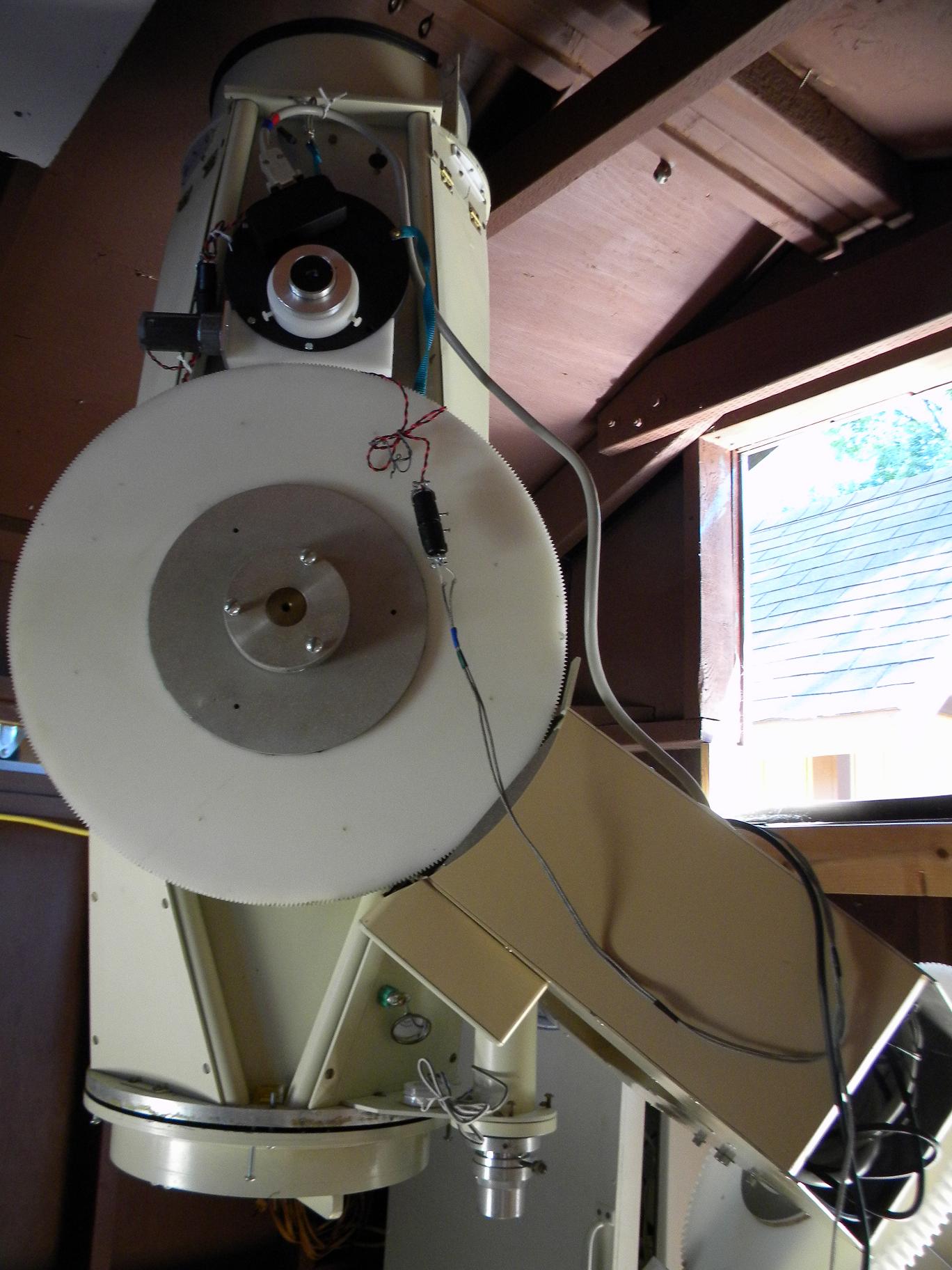
Fig. 8. 9 inch Wright showing truss tube, camera holder with filter wheel, and eyepiece where CCD camera is placed.
The
truss is visible at top and bottom; on the camera side the struts are
separated enough to make room for the focuser and for camera, filter
wheel, etc. The mount is now a fork. The camera is used unguided at
present. The telescope is located in a roll-off roof structure; a gate
to the south opens up, allowing the roof to move over the telescope,
which has to be placed in a horizontal stow position. Two worm gears
provide for the motions; they are cut from HDPE plastic. The
declination wheel was cut by a tap and the plastic held in a jig to let
the tap advance the blank as the threads were cut. Naturally, they
don't come out to a whole number of teeth; the discontinuity is hidden
where the telescope doesn't go. For the polar worm, I used the jig
shown below to gash the teeth.
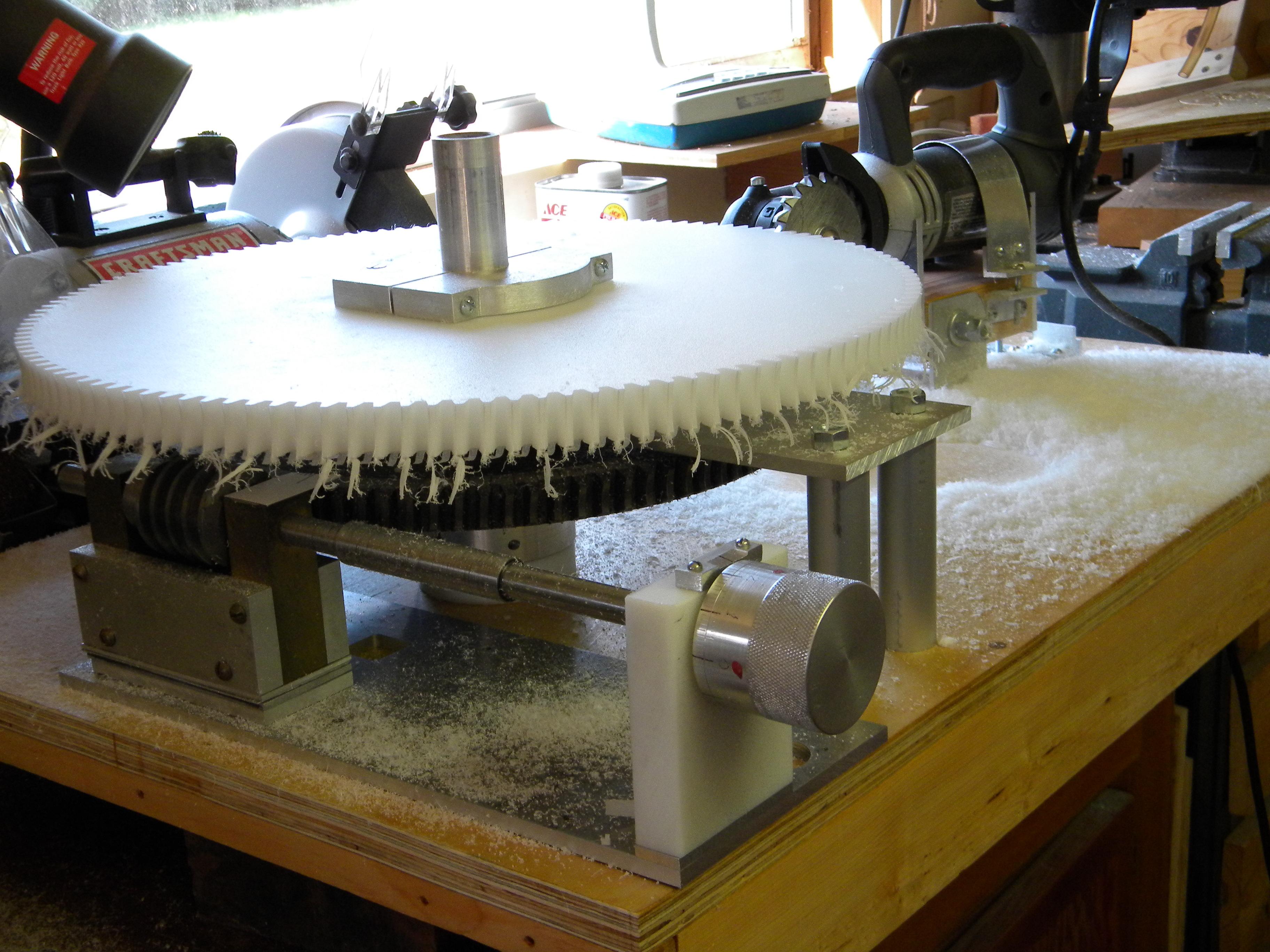
Fig.
9. Gashing the polar worm wheel using a small circular saw with
hand-filed cutter Chicago 12 in. worm wheel used to index.
The
gashing was indexed using a 12 inch worm gear with 96 teeth. I wanted
120 teeth in the 16 inch blank, and so had to turn the worm 0.8 turn
for each tooth. The shape of the cutter was made to match the
commercial (Chicago Gear Works) 8-pitch gear. I had to hand-cut and
file the cutting teeth. (It didn't chatter too badly!) The cutter has
to be tilted slightly to match the worm. I simply bought an 8-pitch
Chicago worm to use in the telescope. After the gear was mounted on the
telescope, and the gear box was in place, I attached a 1/2 inch power
drill to the shaft extension, and drove the gear (not clamped to the
telescope!) while directing a heat gun to the worm. This works nicely.
Be careful to allow this to run several minutes after removing the heat.
References
Palomar Sky Survey - https://en.wikipedia.org/wiki/National_Geographic_Society_%E2%80%93_Palomar_Observatory_Sky_Survey
Edgar Everhart test method - https://www.osapublishing.org/ao/abstract.cfm?uri=ao-5-5-717
Bob May vacuum method - http://bobmay.astronomy.net/vacpan/vacpan.htm
Mathematical treatment - http://www.considine.net/drowesmi/vacmath/schmath2.htm
Everhart's telescope - https://www.guffeyschool.org/resources/observatory/index.html
Serrurier truss - https://en.wikipedia.org/wiki/Serrurier_truss


